Ever wanted to get a list of best C++ practices? Well look no further. Kudos to Urs Enzler for creating it.

C++ STL Container Cheat Sheet
While meandering across the internet, I found this really cool chart: it helps you select which of the C++ STL containers to use in function of a set of desired criteria. Check it out!

C++ STL Cheat Sheet.
Cold Frame Monitor

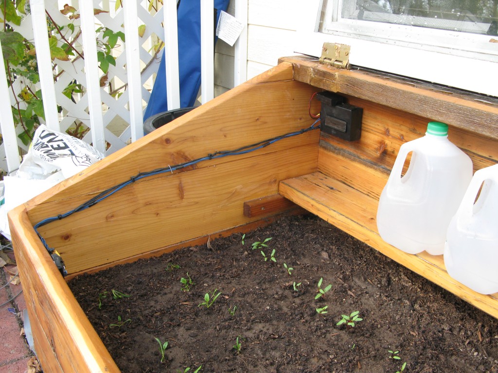
We (household members and I) have recently ordered a handmade cold frame made of recycled household building materials. These little boxes are pretty cool: by relying solely on passive solar energy, one can grow all sorts of food during the winter months (e.g. spinach and lettuce). This particular cold frame came with a shelf where water jugs can sit and absorb additional energy from the sun to help increase the inside temperature of the cold frame at night.
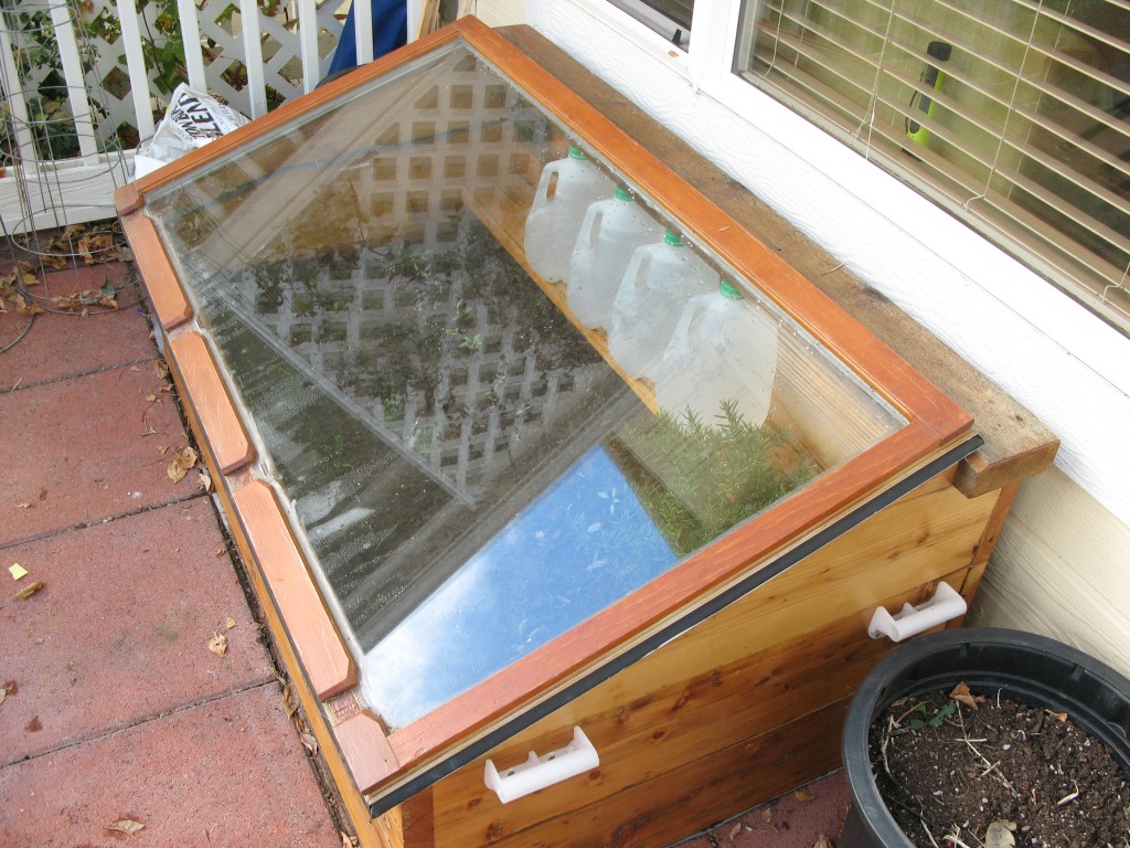
Cold Frame, with water jugs on shelf.
Anticipating the cold winter ahead, it became immediately apparent that we would need to ensure that the cold frame was neither too hot during the day nor too cold at night. While I’m certain that there exist products that monitor temperature over time, why buy something when you can build one? Thus began the cold frame project.
I built a small controller using an existing 16×2 character LCD, two PIC18F14K22, a 32kHz quartz oscillator, a temperature sensor, and a bit of C code. As an added bonus, I got my hands on a humidity sensor sold by Sparkfun and decided to track humidity as well. Using a few small breadboards, the whole thing was wired in a day.
The controller breadboard (pictured below) used two PIC18s: the one on the left connects to the 16×2 character LCD display/backlight and communicates to the right PIC18 over SPI. The right PIC18 connects both the temperature and humidity sensors to an ADC pin and powers the 32kHz oscillator to keep track of time. Two push button are also wired to this latter PIC to allow the user (i.e. us) to set/update the time.
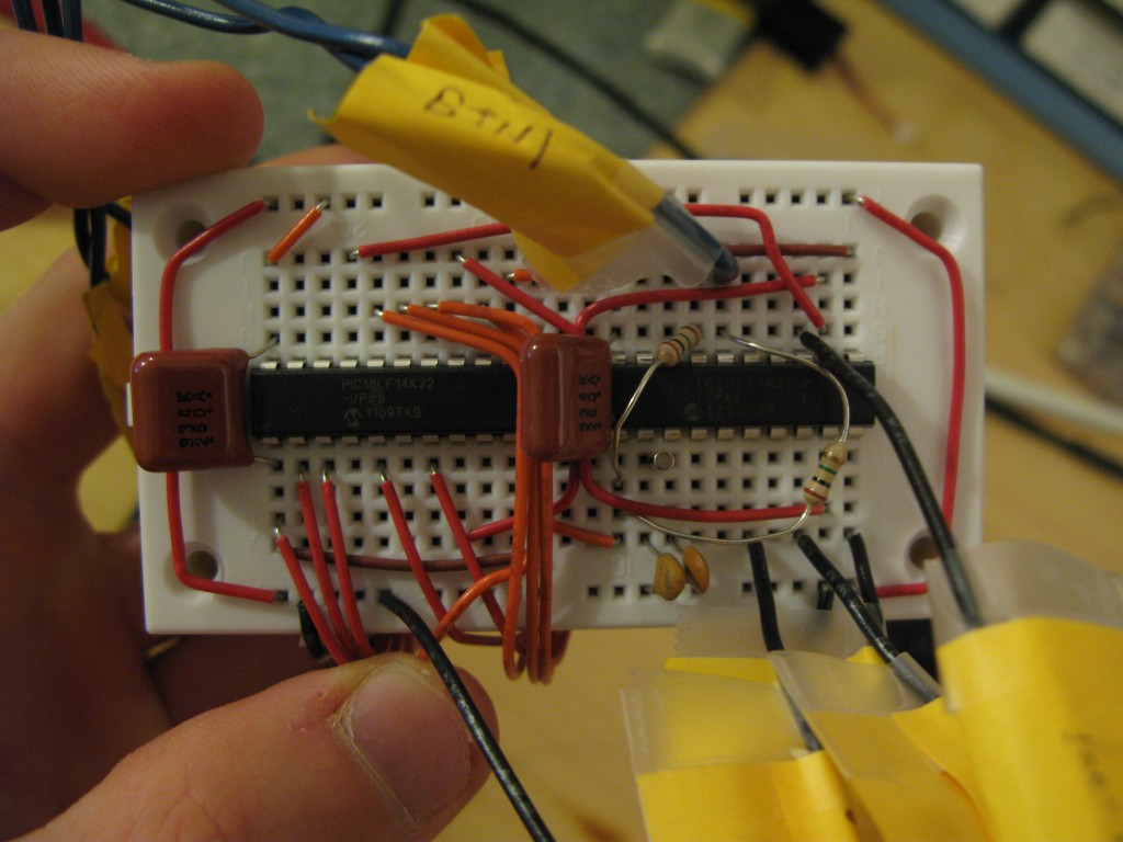
Controller breadboard.
Normally, a single microcontroller with more GPIO pins could be used to do the task of both PICs (and with more ease), but this project is part of “Operation Get Rid of Stuff”, and look: now I used two PICs instead of one, that’s twice as many things no longer in the house!
On the back side of the controller is the display breadboard (pictured below) that wires the LCD display and a small boost converter from Sparkfun to provide a 3.3V rail for the LCD and controller from two AA batteries.
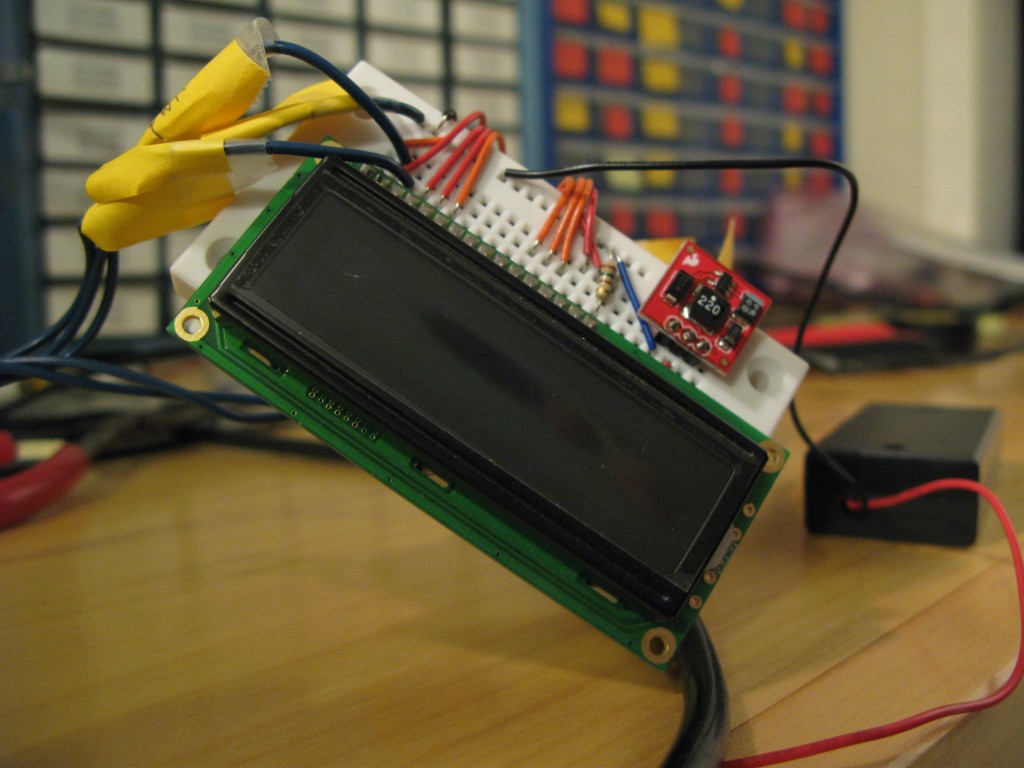
Display breadboard.
A wire harness goes from the controller board to the temperature and humidity sensors, which are both wired on a separate breadboard (pictured below). The humidity sensor is on the left, while the temperature sensor (MCP9700A) is on the right. Sandwiched between the two sensors is an additional boost converter to step-up the voltage from 3.3V to 5V, needed by the humidity sensor. The supply rails for both the temperature sensor and the humidity sensor stay off for a whole minute, and at the end of the minute are turned on for a short period of time. During this time, the microcontroller reads the temperature and humidity and records the data. Once sampled, the sensors are once again disabled to save precious battery life.
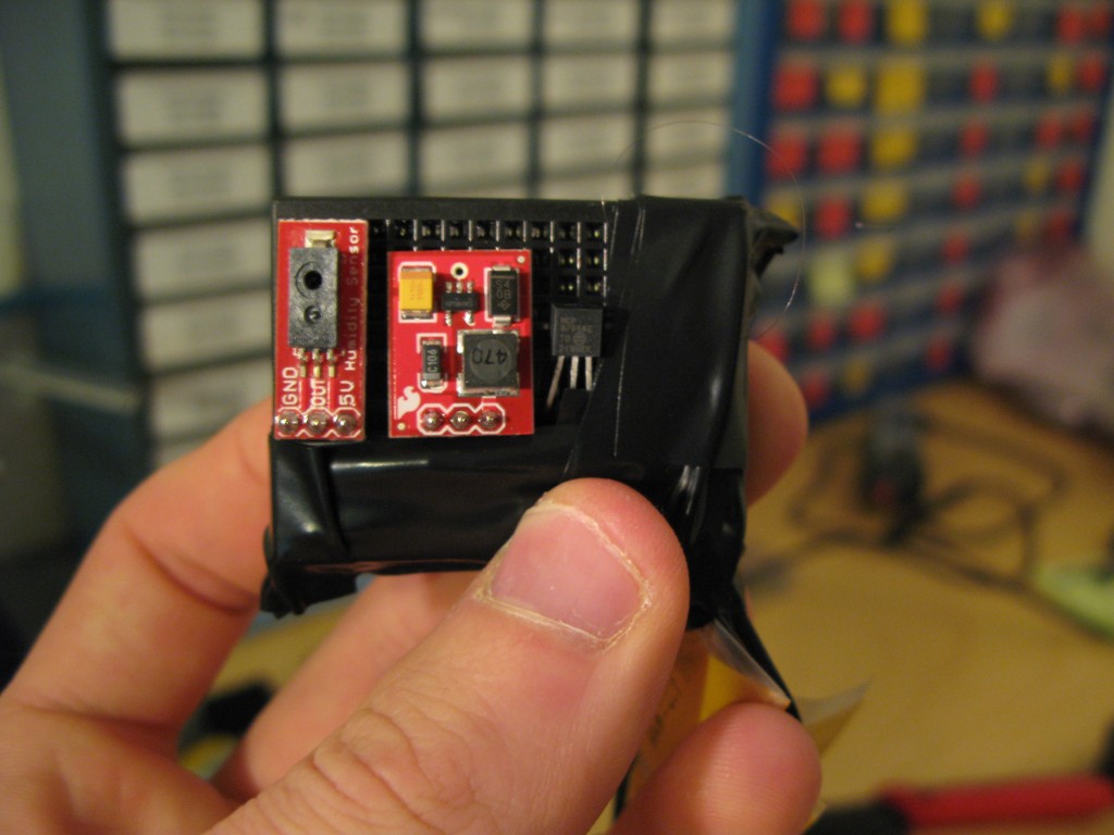
Temperature and humidity breadboard.
The interface breadboard wires two buttons and a potentiometer for the LCD contrast. Nothing too magical here. Pressing the blue button enables the LCD display and shows a marquee of the the current , maximum, and minimum temperature and humidity readings. Pressing the white button sets the time by incrementing it by 10 minutes on each button press. As a safety feature, the white button does not respond unless the blue button is first pressed. This prevents the us from accidentally setting the time.
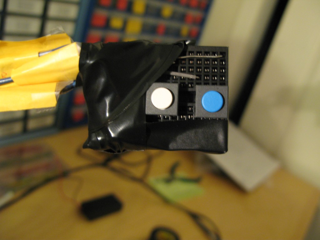
Interface breadboard.
Now I may make this look easy, but packaging the controller and display board in a project box was actually pretty challenging. It ended up being a really tight fit, with a lucky dremel cut for the LCD to poke through.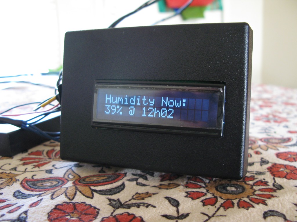
- Controller and Display boards inside a project box. 39% humidity: it’s pretty dry here…
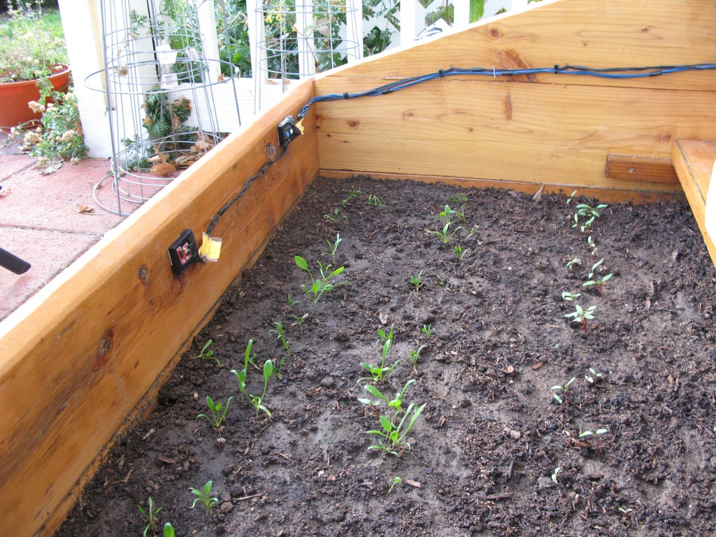
Last but not least: placing the whole project in the cold frame. The project box nailed to the cold frame’s back walls using two nails on the bottom of the box and one on top.
The wire harness is hammered in place using nails as well. The nails are hammered part way in and then bent upwards, cupping the wires to prevent them from falling off.
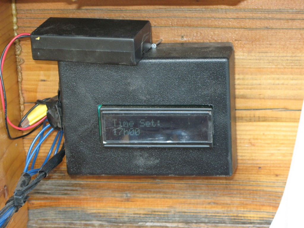
Setting controller time in the cold frame.
Macgyver wire harness to interface and sensor breadboards.
Lastly, the sensor and interface breadboards are connected to the cold frame with a double sided adhesive surface (update: this adhesive turned out to be a bad idea. The cold frame’s high humidity (around 98% max) slowly unglues the breadboards from the wall).
Interface board (right) and sensor board (left).
And voila, mission accomplished! All in all, this project took about 2 days to complete. Not only have I successfully managed to rid my lab space of quite a few breadboards, PICs, and parts which were collecting dust, but I’ve managed to do so while providing a useful measuring tool for growing plants over winter. We use this monitor on a daily basis, especially in the morning, after the controller collected data from the previous night.
The controller’s quiescent draw turned out to be remarkably low as well. When the controller is not displaying the marquee, the LCD is disabled, the backlight is turned off, the sensors are unpowered, and the microcontroller remains in a deep sleep mode, waking up only once a minute to enable and read the sensors. This makes the overall quiescent current of the whole system very small (update: thus far two AA batteries have lasted over 4 months and are still truckin’).
And in case you are wondering, the min and max temperature/humidity are reset daily at 3pm and 3am respectively.
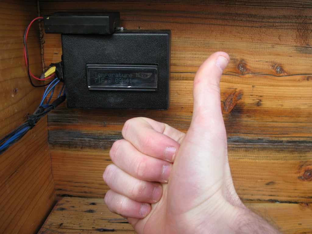
Mission accomplished!
Tagged with: Battery, Breadboard, Cold Frame, Corner, Humidity, Jonathan, Jonathan's Corner, LCD, Liquid Crystal Display, Monitor, PIC18F14K22, Sensor, Sparkfun, Temperature
Posted in Jonathan's Corner
Posted in Jonathan's Corner
Halloween LEDs

There comes a time in a mouse’s life when it is no longer a mouse: it transpires away from the realm of the living and joins the ever increasing pile of electronics junk.
My mouse, computer mouse that is, gave its last breath not too long ago. In the midst of an intense Portal2 Co-Op session, my mouse suddenly decided that it would no longer acknowledge any my clicks, irrespective of how hard I pressed the buttons. Thankfully, spare mice are plentiful in these parts, and it wasn’t long until the Portal2 endeavor vigorously ensued.
I suppose that in normal circumstances I should have felt at least a bit sad about my loss, but instead I couldn’t wait to open it up and figure out the decorative multi-color LED was wired (this video illustrates this feature).
After cracking the mouse open, I was surprised to find that the LED only had two leads instead of the standard four. Aha! This is one of those integrated LEDs: and sure enough, wiring straight to 5V produced the ever changing color patterns. Very simple to wire up, entertaining to watch, but not terribly useful to keep around: unless of course Halloween is around the corner.
Carve a pumpkin (there’s a great online tutorial on how to carve amazing looking pumpkins), wire up the LED, and you got yourself a groovy jack-o-lantern.

Integrated RGB LED wired to a 5V boost circuit from Sparkfun and batteries.

Carving a Pumpkin.

Integrated RGB LED circuit inside the pumpkin.
Mission accomplished, unless, of course, you have two carved pumpkins. It simply wouldn’t be fair for the other pumpkin to not have any cool LEDs as well. The second pumpkin, carved by my lovely assistant, is pretty evil looking. Groovy LEDs don’t go well with evil pumpkins, but it’s nothing a small PIC and a few spare LEDs can’t fix.

Evil pumpkin, and friend.
For this project, you’ll need:
- A small breadboard (something like this would do)
- A 0.1uF ceramic capacitor.
- A 4.7k-10kOhm resistor.
- Five 220Ohm resistors.
- Five LEDs of your choice (preferably of different colors).
- A 3.3V or 5V boost converter (Sparkfun builds a great little boost converter)
Wire them up like this:

Halloween LED Schematic
And with the little snippet of code below, you got yourself a pretty angry multi-colored LED pattern.
|
1 2 3 4 5 6 7 8 9 10 11 12 13 14 15 16 17 18 19 20 21 22 23 24 25 26 27 28 29 30 31 32 33 34 35 36 37 38 39 40 41 42 43 44 45 46 47 48 49 50 51 52 53 54 55 56 57 58 59 60 61 62 63 64 65 66 67 68 69 70 |
/* * File: main.c * Author: Jonathan Bruneau * * Created on October 26, 2012, 10:52 AM */ #pragma config FOSC = IRC //Internal RC oscillator #pragma config MCLRE = ON //MCLR is enabled to allow for ISCP. #pragma config LVP = OFF //Single Supply ISCP disabled. #pragma config STVREN = ON //Stack overflow will cause a reset. #pragma config XINST = OFF //Extended instruction set disabled. #include "xc.h" #include "stdlib.h" #include "stdint.h" //The port mask for blink LEDs #define PORT_MASK 0x1F //Set the timer to the specified elapsed time. #define set_timer(x) do{TMR0L = (uint8_t)x;}while(0) //Turn the LEDs on/off in function of the specified value. #define set_leds(x) do{LATC = (LATC & ~PORT_MASK) | ((x) & PORT_MASK);}while(0) void interrupt high_isr(void) { //Clear timer interrupt. INTCONbits.TMR0IF = 0; { //Generate random value once, and use said value to set the timer and the LEDs. const uint16_t x = rand(); set_timer(x); set_leds(x); } } int main(int argc, char** argv) { //Set the oscillator to a *really* slow speed to save on power. OSCTUNEbits.INTSRC = 0; OSCCONbits.IRCF = 0x0; //Seed the random value generator. srand(0); //Make the processor go to IDLE when a sleep command is received. //(This allows Timer0 to continue operation). OSCCONbits.IDLEN = 1; //Set PORT C0, C1, C2, C3, and C4 to outputs. TRISC &= ~PORT_MASK; //Setup Timer T0CONbits.T0CS = 0; //Use internal oscillator as clock source. //T0CONbits.T0PS = 0x5; //1:32 prescaler. Increase the prescaler if it's the holidays. //T0CONbits.PSA = 0; //Use prescaler. INTCONbits.TMR0IE = 1; //Enable timer0 interrupts. set_timer(rand()); //Set the timer to an initial value. T0CONbits.TMR0ON = 1; //Enable the timer. //Enable global interrupts. INTCONbits.GIEL = INTCONbits.GIEH = 1; while(1) Sleep(); } |

Multi-Color LED breadboard for evil pumpkin.
What the code does, in essence, is initialize Timer0 of the PIC18 to a random value, and starts the timer. On every timer interrupt, a random value is assigned to the LEDs (wired to PORTC0 to PORTC4), and a new random value is assigned to the timer. The LEDs thus turn on/off randomly, and at a random intervals. The end effect is pretty cool, to say the least. But don’t take my word for it: check it this video that show both pumpkins in action.
Notice that the Timer0 prescaler is off. If you want the LEDs to change more slowly (say, because the holidays are soon coming), uncomment these two lines in the main() routine, and the end result will be much more soothing.
|
1 2 3 4 5 |
//Setup Timer T0CONbits.T0CS = 0; //Use internal oscillator as clock source. T0CONbits.T0PS = 0x5; //1:32 prescaler. Increase the prescaler if it's the holidays. T0CONbits.PSA = 0; //Use prescaler. INTCONbits.TMR0IE = 1; //Enable timer0 interrupts. |
Needless to say, these little pumpkins turned out great. Happy Halloween!
Happy Halloween!
Tagged with: Boost, Breadboard, Button, Halloween, Jonathan, Jonathan's Corner, LED, Light, PIC18F14K22, Pumpkin, Sparkfun
Posted in Jonathan's Corner
Posted in Jonathan's Corner
Building a Solar Powered Light
As this is my first post for the TeraCharge website, I think a bit of history is in order (I promise I’ll keep it short).
When I’m not at work, or out snowboarding/mountain biking, I typically find myself in a little corner of my house fondly referred to as the “Laboratory”. What started as a small assortment of chips, resistors, and capacitors later became an uncontrollable mess of ICs of all kinds, boost caps, power resistors, etc . (this chaos was facilitated by an accidental (and welcomed) acquisition of a very large array of 7400 series parts). Other members of the household have discovered by their own means to steer clear of this corner, and as such this became my corner: Jonathan’s Corner.
A few months back I was informed by a key house member that the Lab was getting a little out of hand and that parts had to stop coming in and had to start leaving. Thus began “Operation Get Rid of Stuff”, which commenced with a simple project: building a light.

Jonathan’s Corner, a.k.a “The Laboratory”
The back of our house had no exterior lights, which made unlocking the back door at night a challenging endeavor to say the least. We intended on purchasing some kind of exterior light when it occurred to me that I had more than enough parts laying around to build a solar powered light. With proper hacks to an old PCB, I could make it work.
This PCB was an circuit that I had made for some friends a while back to learn how to solder and do some basic C programming. It wired four buttons and four seven segment displays (SSD) to a PIC18F14K22 processor, with a solar lithium polymer charging circuit. I luckily had two PIC18s, a few buttons, SSDs, and a spare 0.5W solar panel. All I needed was to create a small daughter board for white LEDs (which I also had collecting dust) and somehow solder it on the main PCB to make it a fully functional solar light.

PCB to hack.
Although this project was done using an old PCB, it could easily be wired on a breadboard. The parts required to do this are:
- A PIC18F14K22 (great little PICs by the way).
- A BCD to Seven Segment Display (SSD) Decoder: something like a 74HC4511. I luckily found in surplus (and thus for cheap) MC14543B, which are BCD to SSD ICs with fancy LED driving circuitry and latching inputs. On Semiconductors actually still make these; they make for great for any simple SSD based projects.
- 5V solar cells. Sparkfun sells a really nice 0.5W that is terminated with a barrel plug.
- A Lithium Polymer (LiPo) battery. You can find some once again at Sparkfun.
- The MAX1555 Lithium Polymer Charger (a very nice, cheap charger in SOT23-5). Sparkfun sells an adapter such that the part can be placed on a breadboard.
- A momentary push button.
- At least two Seven Segment Displays.
- A whole bunch of 330Ohm resistors.
- About six white LEDs.
- One 4.7K-10KOhm resistor.
- Five 10k-1MOhm resistors.
- Two 1uF capacitors.
- Two 0.1uF capacitors.
- A PMOS (or, preferably, a NMOS).
- Four NMOSs.
- (Optional) A red LED and a switch.
The schematic for the solar battery charger is pretty simple, and uses the extremely handy MAX1115 Lithium Polymer charger IC. For real simple charging, the MAX1555 can’t be beat.

5V Solar Lithum Polymer charging circuit.
Wire the 5V solar panel straight into the MAX1555 DC input, the battery to the BAT output, and voilà, you are charging a battery (doesn’t get easier than that)! The red LED is optional: whenever the MAX1555 is actively charging the battery, it will pull down the CHG’ signal, thus turning on the LED. Note that if you are building this circuit for yourself, you will want the ability to switch off the LED (hence the switch in the schematic): otherwise, a great deal of energy used to charge the battery will instead go to the LED.
The SSD display portion of the PCB uses the MC14543B to convert a BCD value to its corresponding SSD representation. The MC14543B is designed to run a variety of SSD displays (including LCDs) and has latching inputs, although they are all disabled on the schematic. Really, a 74HC4511 could have been used.

SSD Display
The outputs of the MC14543B are wired to all four SSDs, and in turn each SSD’s COM pins are wired to an NMOS. The NMOSs are controller by the PIC18, which turns one of them on one at a time, in sequence, and very quickly. Whenever the NMOS is OFF, the LEDs for said SSD are off. If the NMOS is on, the corresponding segments of the SSD are turned on in function of the BCD value on the LA, LB, LC, and LD signals. As such, each SSD can display a separate and unique value, using only one BCD to SSD IC. The values for the resistor tied to the NMOSs’ gate (R2-R8) are pretty arbitrary, and given the generally slow strobe speed of the SSD display, don’t really matter.
The SSD display, along with a single button, are connected to the PIC18. No magic here. Notice that the 4.7KOhm resistor used for the ICSP can be any value between 1K to 10K, according to Microchip.

PIC18 connections to the remainder of the schematic.
The light functions as follows:
- The circuit is initially off and in a low power mode (all lights are off, and the processor is in sleep mode). This allows the maximum amount of energy from the sun to charge the battery during the day.
- When night falls, and we need light, I press the lone button populated on the PCB.
- The button press activates the white LEDs for 15 seconds. Subsequent button presses add another 15 seconds to the total time, and the time counts down to zero. The time is shown on the SSD display.
- Once the elapsed time expired (i.e. the countdown reaches zero), the circuit returns to a low power state, and the LEDs turn off.
First, I built the white LED daughter board. I had a logic level TO-220 30V PMOS lying around which I used to power on the LEDs (I would have preferred using an NMOS, but I had none at the time. I have since addressed the issue, to some household members’ dismay). The schematic is very similar to the NMOS schematic used on the SSD display.

White LED daughter board schematic.

Front side of white LED daughter board.

Back side of white LED daughter board.
Much like the NMOSs, the 1MOhm and the 330Ohm resistors values can be changed because we have no speed requirement for turning the PMOS on/off (the astute observer will notice that the values on the back side of the daughter board are actually different). The ballast resistor for the white LEDs (R21) is selected such that at 5V, every LED gets around 10mA. In an ideal world, each LED would share current equally. In reality, however, LEDs tend to have poor I-V characteristics (even in LEDs from the same production batch), which leads them to not share current equally (more on this later). For this project, I don’t really care, but in some applications this can be a big deal.
I then wired the daughter board on the PCB and soldered the PIC, the BCD-SSD IC, the button, and the four SSDs to the PCB.
After a little bit of C code for the PIC18, I had a completed project.

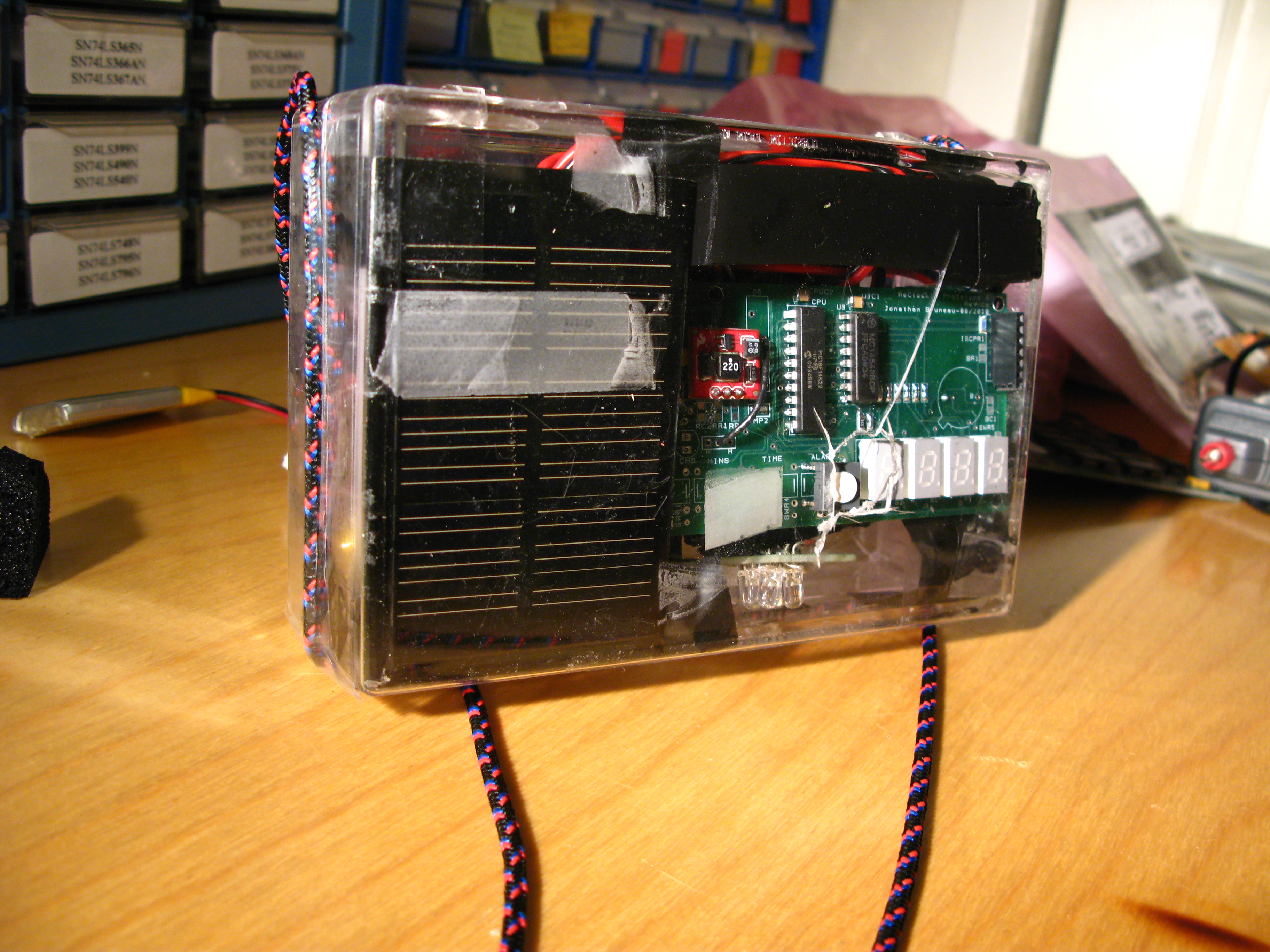
Project Complete!
That little red PCB on the upper left of the green PCB is a 5V boost converter built by Sparkfun. Fantastic little thing, and well worth the price. It’s not needed for this project, but I only had a -5V Vgs(th) PMOSs available at the time, too large a value for the LiPo’s voltage to fully turn the PMOS on. Boosting the voltage to 5V solves this issue. To save on cost, I would instead recommend getting a smaller Vgs(th) PMOS and running this project unregulated (as shown in the schematic). Yes, the white LEDs will progressively dim as the battery voltage slowly drops, but the underlying battery life will be greatly increased.
Since this thing had to go outside and survive that harsh suburban wilderness, I couldn’t leave the circuit exposed in such a fashion: any kind of precipitation would effectively destroy the project (and my morale) in seconds. So I looked through the scrap pile and found a heavily damaged (but useable) clear acrylic project box. It had a hole in it, but I could enlarge it to let the button to poke through. It took a bit of finagling and lots of electrical tape to get it in there, but it fit.
Ugly boxing job, but hey… it works!
I used some leftover weight bearing rope to hang the light from a nail on the wall. It’s now been happily hanging by our door and gets daily usage. It will be interesting to see how the light will function in winter, given the shorter days and the harsher LiPo operating temperatures.

Outside and working. Only 14 seconds to go!