There comes a time in a mouse’s life when it is no longer a mouse: it transpires away from the realm of the living and joins the ever increasing pile of electronics junk.
My mouse, computer mouse that is, gave its last breath not too long ago. In the midst of an intense Portal2 Co-Op session, my mouse suddenly decided that it would no longer acknowledge any my clicks, irrespective of how hard I pressed the buttons. Thankfully, spare mice are plentiful in these parts, and it wasn’t long until the Portal2 endeavor vigorously ensued.
I suppose that in normal circumstances I should have felt at least a bit sad about my loss, but instead I couldn’t wait to open it up and figure out the decorative multi-color LED was wired (this video illustrates this feature).
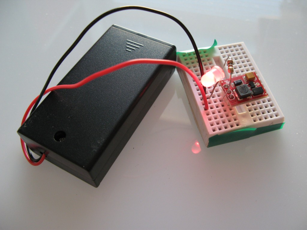
After cracking the mouse open, I was surprised to find that the LED only had two leads instead of the standard four. Aha! This is one of those integrated LEDs: and sure enough, wiring straight to 5V produced the ever changing color patterns. Very simple to wire up, entertaining to watch, but not terribly useful to keep around: unless of course Halloween is around the corner.
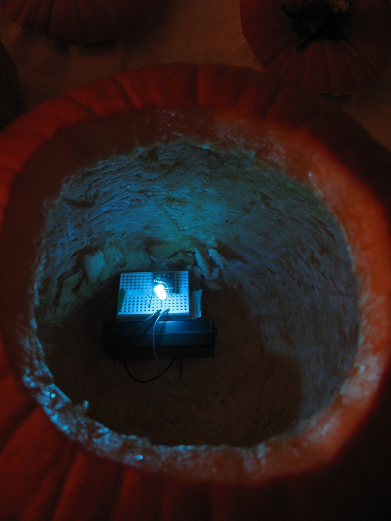
Carve a pumpkin (there’s a great online tutorial on how to carve amazing looking pumpkins), wire up the LED, and you got yourself a groovy jack-o-lantern.
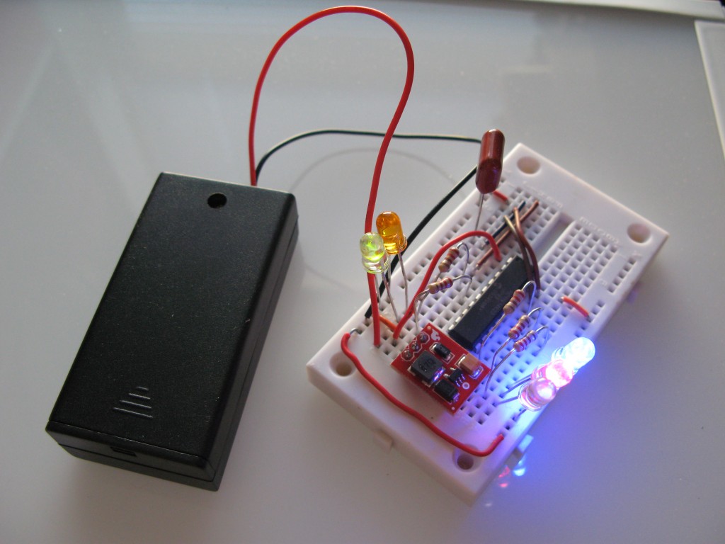
Mission accomplished, unless, of course, you have two carved pumpkins. It simply wouldn’t be fair for the other pumpkin to not have any cool LEDs as well. The second pumpkin, carved by my lovely assistant, is pretty evil looking. Groovy LEDs don’t go well with evil pumpkins, but it’s nothing a small PIC and a few spare LEDs can’t fix.
For this project, you’ll need:
- A small breadboard (something like this would do)
- A 0.1uF ceramic capacitor.
- A 4.7k-10kOhm resistor.
- Five 220Ohm resistors.
- Five LEDs of your choice (preferably of different colors).
- A 3.3V or 5V boost converter (Sparkfun builds a great little boost converter)
Wire them up like this:
And with the little snippet of code below, you got yourself a pretty angry multi-colored LED pattern.
|
1 2 3 4 5 6 7 8 9 10 11 12 13 14 15 16 17 18 19 20 21 22 23 24 25 26 27 28 29 30 31 32 33 34 35 36 37 38 39 40 41 42 43 44 45 46 47 48 49 50 51 52 53 54 55 56 57 58 59 60 61 62 63 64 65 66 67 68 69 70 |
/* * File: main.c * Author: Jonathan Bruneau * * Created on October 26, 2012, 10:52 AM */ #pragma config FOSC = IRC //Internal RC oscillator #pragma config MCLRE = ON //MCLR is enabled to allow for ISCP. #pragma config LVP = OFF //Single Supply ISCP disabled. #pragma config STVREN = ON //Stack overflow will cause a reset. #pragma config XINST = OFF //Extended instruction set disabled. #include "xc.h" #include "stdlib.h" #include "stdint.h" //The port mask for blink LEDs #define PORT_MASK 0x1F //Set the timer to the specified elapsed time. #define set_timer(x) do{TMR0L = (uint8_t)x;}while(0) //Turn the LEDs on/off in function of the specified value. #define set_leds(x) do{LATC = (LATC & ~PORT_MASK) | ((x) & PORT_MASK);}while(0) void interrupt high_isr(void) { //Clear timer interrupt. INTCONbits.TMR0IF = 0; { //Generate random value once, and use said value to set the timer and the LEDs. const uint16_t x = rand(); set_timer(x); set_leds(x); } } int main(int argc, char** argv) { //Set the oscillator to a *really* slow speed to save on power. OSCTUNEbits.INTSRC = 0; OSCCONbits.IRCF = 0x0; //Seed the random value generator. srand(0); //Make the processor go to IDLE when a sleep command is received. //(This allows Timer0 to continue operation). OSCCONbits.IDLEN = 1; //Set PORT C0, C1, C2, C3, and C4 to outputs. TRISC &= ~PORT_MASK; //Setup Timer T0CONbits.T0CS = 0; //Use internal oscillator as clock source. //T0CONbits.T0PS = 0x5; //1:32 prescaler. Increase the prescaler if it's the holidays. //T0CONbits.PSA = 0; //Use prescaler. INTCONbits.TMR0IE = 1; //Enable timer0 interrupts. set_timer(rand()); //Set the timer to an initial value. T0CONbits.TMR0ON = 1; //Enable the timer. //Enable global interrupts. INTCONbits.GIEL = INTCONbits.GIEH = 1; while(1) Sleep(); } |
What the code does, in essence, is initialize Timer0 of the PIC18 to a random value, and starts the timer. On every timer interrupt, a random value is assigned to the LEDs (wired to PORTC0 to PORTC4), and a new random value is assigned to the timer. The LEDs thus turn on/off randomly, and at a random intervals. The end effect is pretty cool, to say the least. But don’t take my word for it: check it this video that show both pumpkins in action.
Notice that the Timer0 prescaler is off. If you want the LEDs to change more slowly (say, because the holidays are soon coming), uncomment these two lines in the main() routine, and the end result will be much more soothing.
|
1 2 3 4 5 |
//Setup Timer T0CONbits.T0CS = 0; //Use internal oscillator as clock source. T0CONbits.T0PS = 0x5; //1:32 prescaler. Increase the prescaler if it's the holidays. T0CONbits.PSA = 0; //Use prescaler. INTCONbits.TMR0IE = 1; //Enable timer0 interrupts. |
Needless to say, these little pumpkins turned out great. Happy Halloween!


Leave a Reply