
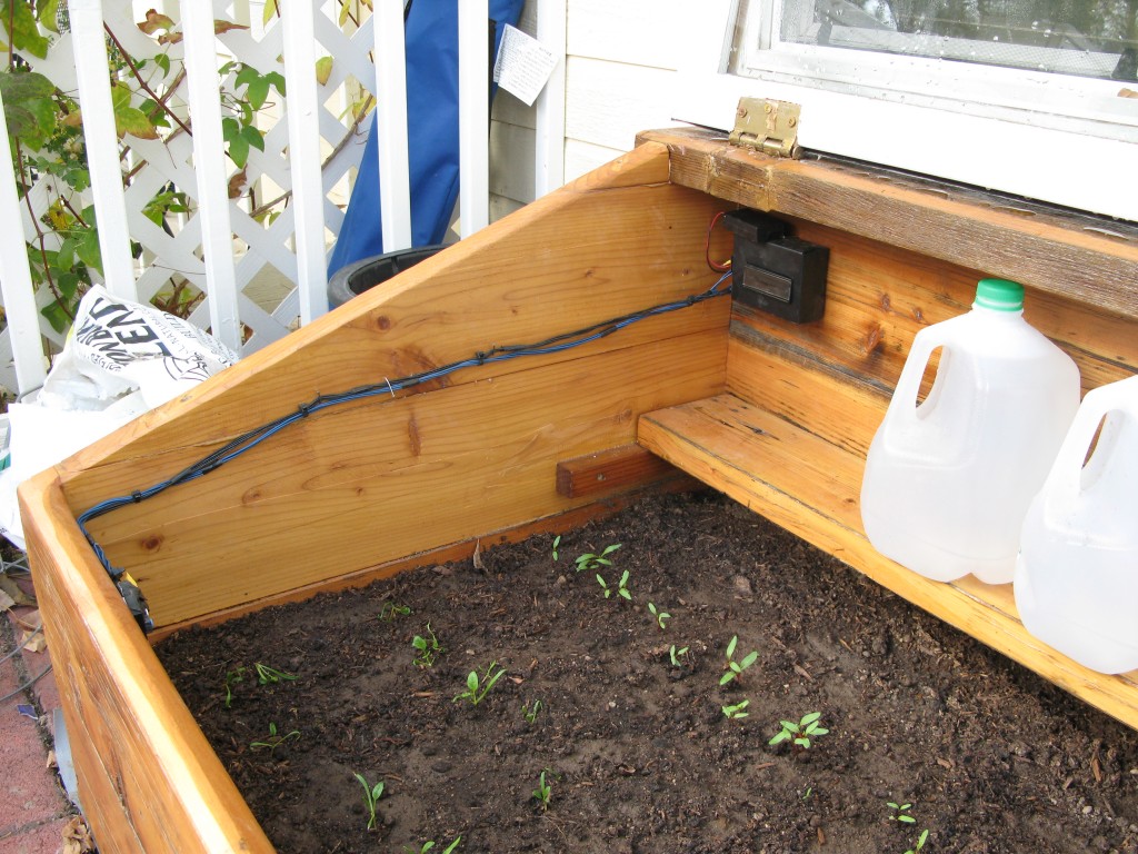
We (household members and I) have recently ordered a handmade cold frame made of recycled household building materials. These little boxes are pretty cool: by relying solely on passive solar energy, one can grow all sorts of food during the winter months (e.g. spinach and lettuce). This particular cold frame came with a shelf where water jugs can sit and absorb additional energy from the sun to help increase the inside temperature of the cold frame at night.
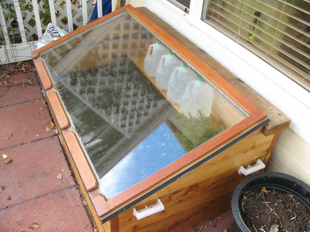
Cold Frame, with water jugs on shelf.
Anticipating the cold winter ahead, it became immediately apparent that we would need to ensure that the cold frame was neither too hot during the day nor too cold at night. While I’m certain that there exist products that monitor temperature over time, why buy something when you can build one? Thus began the cold frame project.
I built a small controller using an existing 16×2 character LCD, two PIC18F14K22, a 32kHz quartz oscillator, a temperature sensor, and a bit of C code. As an added bonus, I got my hands on a humidity sensor sold by Sparkfun and decided to track humidity as well. Using a few small breadboards, the whole thing was wired in a day.
The controller breadboard (pictured below) used two PIC18s: the one on the left connects to the 16×2 character LCD display/backlight and communicates to the right PIC18 over SPI. The right PIC18 connects both the temperature and humidity sensors to an ADC pin and powers the 32kHz oscillator to keep track of time. Two push button are also wired to this latter PIC to allow the user (i.e. us) to set/update the time.
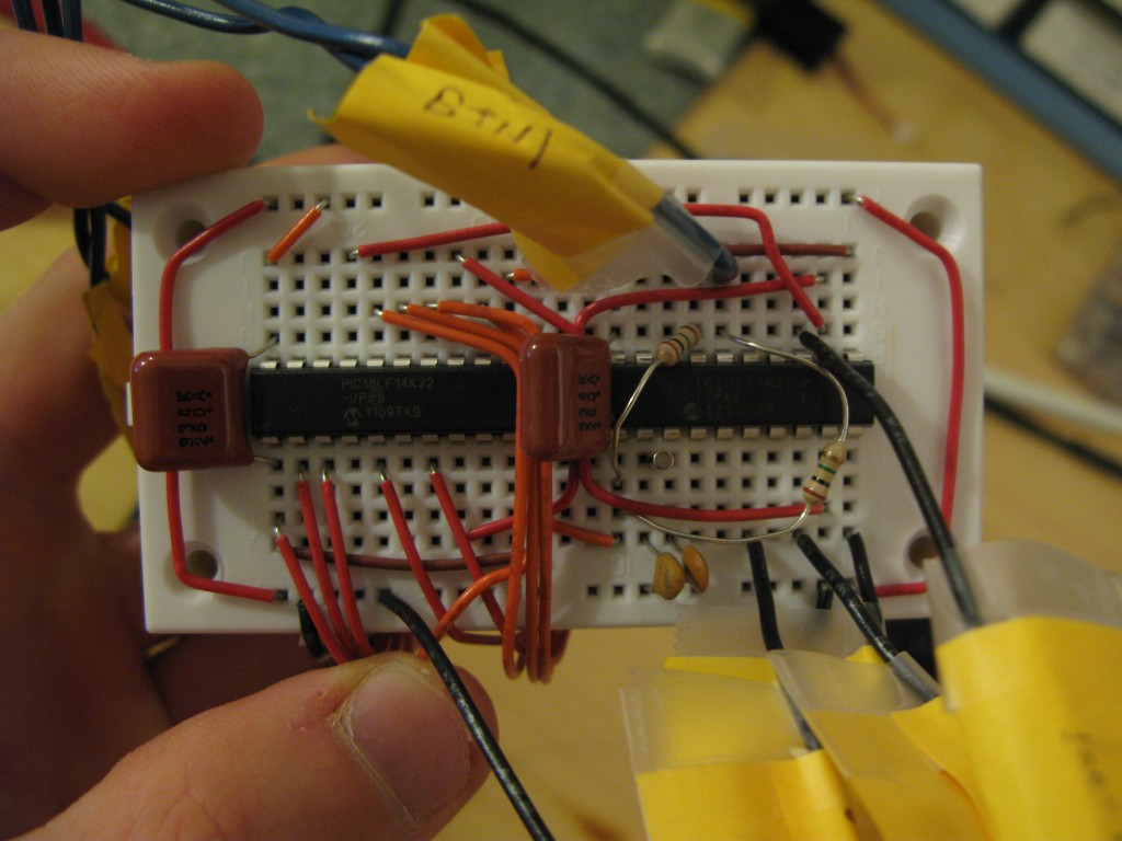
Controller breadboard.
Normally, a single microcontroller with more GPIO pins could be used to do the task of both PICs (and with more ease), but this project is part of “Operation Get Rid of Stuff”, and look: now I used two PICs instead of one, that’s twice as many things no longer in the house!
On the back side of the controller is the display breadboard (pictured below) that wires the LCD display and a small boost converter from Sparkfun to provide a 3.3V rail for the LCD and controller from two AA batteries.
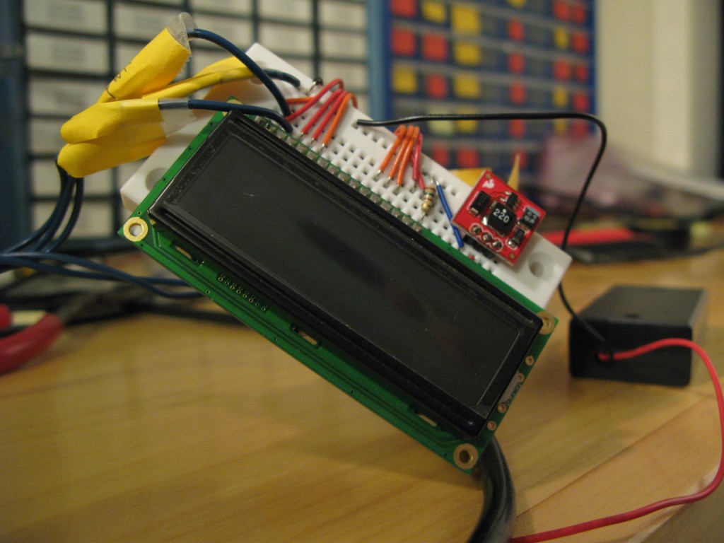
Display breadboard.
A wire harness goes from the controller board to the temperature and humidity sensors, which are both wired on a separate breadboard (pictured below). The humidity sensor is on the left, while the temperature sensor (MCP9700A) is on the right. Sandwiched between the two sensors is an additional boost converter to step-up the voltage from 3.3V to 5V, needed by the humidity sensor. The supply rails for both the temperature sensor and the humidity sensor stay off for a whole minute, and at the end of the minute are turned on for a short period of time. During this time, the microcontroller reads the temperature and humidity and records the data. Once sampled, the sensors are once again disabled to save precious battery life.
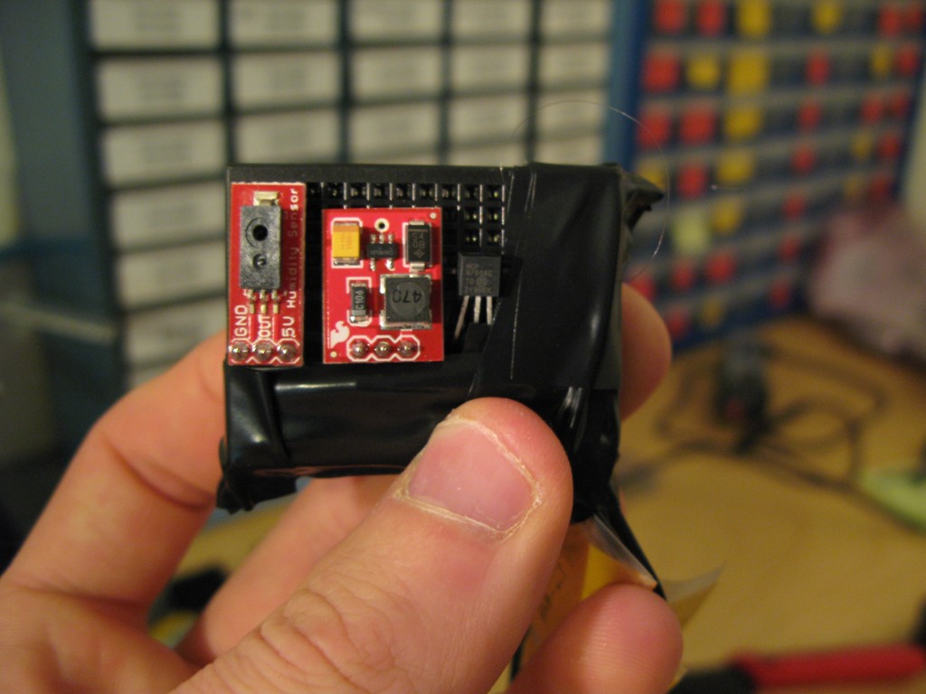
Temperature and humidity breadboard.
The interface breadboard wires two buttons and a potentiometer for the LCD contrast. Nothing too magical here. Pressing the blue button enables the LCD display and shows a marquee of the the current , maximum, and minimum temperature and humidity readings. Pressing the white button sets the time by incrementing it by 10 minutes on each button press. As a safety feature, the white button does not respond unless the blue button is first pressed. This prevents the us from accidentally setting the time.
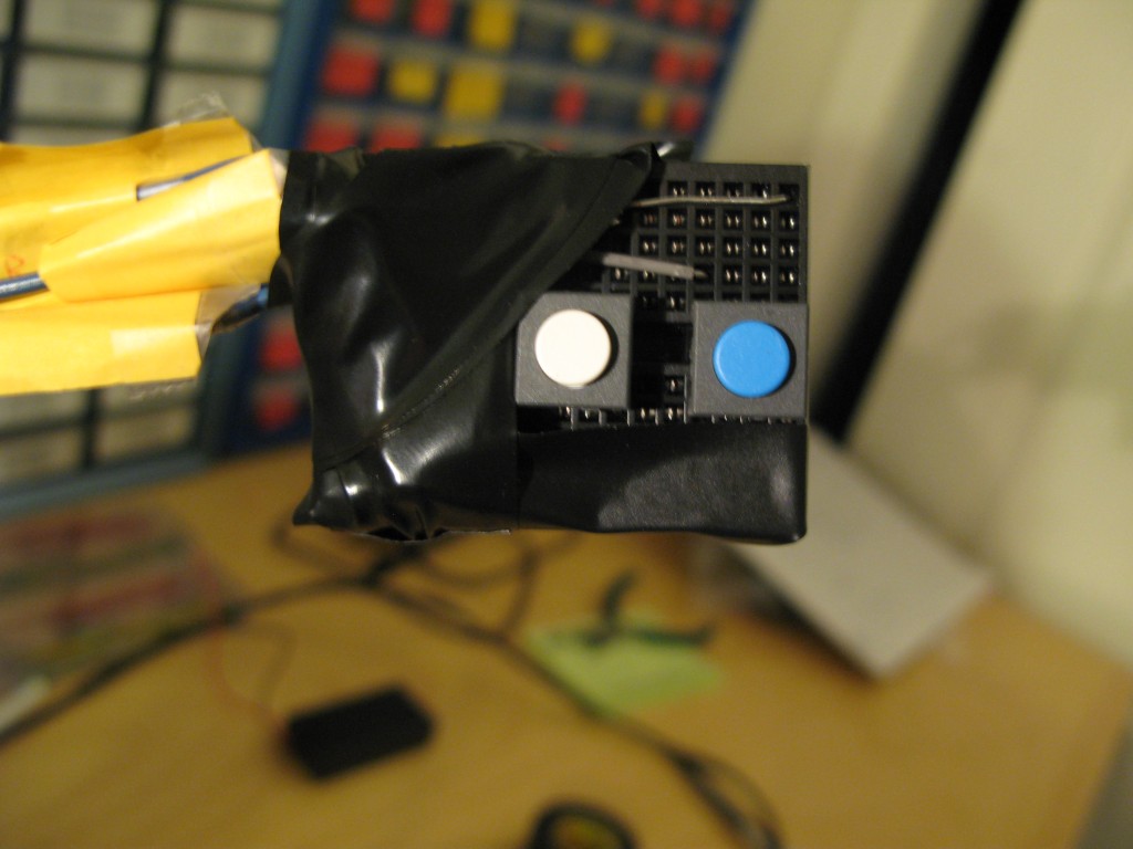
Interface breadboard.
Now I may make this look easy, but packaging the controller and display board in a project box was actually pretty challenging. It ended up being a really tight fit, with a lucky dremel cut for the LCD to poke through.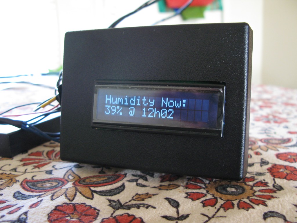
- Controller and Display boards inside a project box. 39% humidity: it’s pretty dry here…
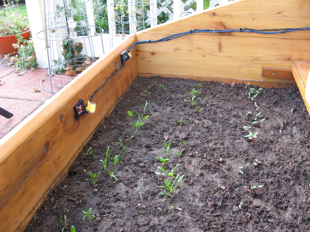
Last but not least: placing the whole project in the cold frame. The project box nailed to the cold frame’s back walls using two nails on the bottom of the box and one on top.
The wire harness is hammered in place using nails as well. The nails are hammered part way in and then bent upwards, cupping the wires to prevent them from falling off.
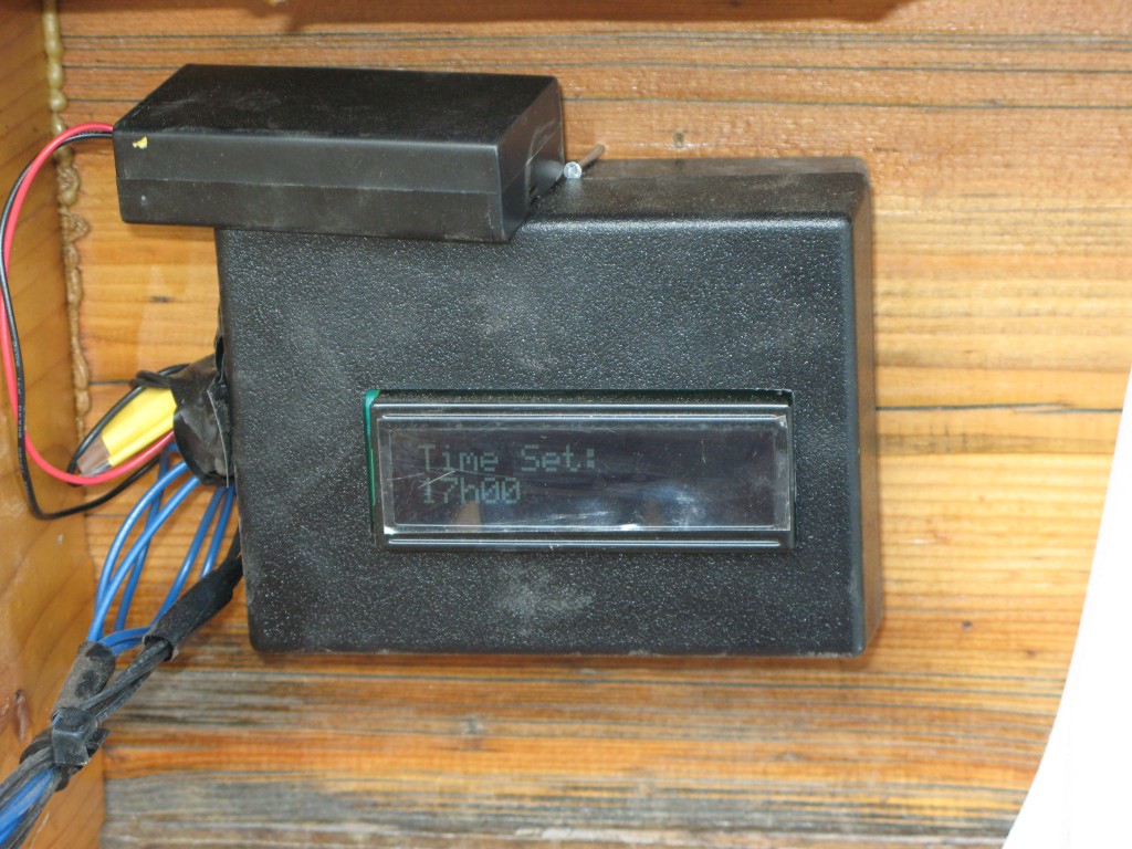
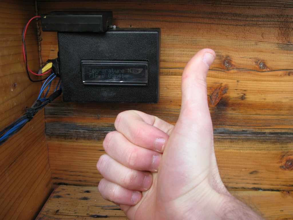
Setting controller time in the cold frame.
Macgyver wire harness to interface and sensor breadboards.
Lastly, the sensor and interface breadboards are connected to the cold frame with a double sided adhesive surface (update: this adhesive turned out to be a bad idea. The cold frame’s high humidity (around 98% max) slowly unglues the breadboards from the wall).
Interface board (right) and sensor board (left).
And voila, mission accomplished! All in all, this project took about 2 days to complete. Not only have I successfully managed to rid my lab space of quite a few breadboards, PICs, and parts which were collecting dust, but I’ve managed to do so while providing a useful measuring tool for growing plants over winter. We use this monitor on a daily basis, especially in the morning, after the controller collected data from the previous night.
The controller’s quiescent draw turned out to be remarkably low as well. When the controller is not displaying the marquee, the LCD is disabled, the backlight is turned off, the sensors are unpowered, and the microcontroller remains in a deep sleep mode, waking up only once a minute to enable and read the sensors. This makes the overall quiescent current of the whole system very small (update: thus far two AA batteries have lasted over 4 months and are still truckin’).
And in case you are wondering, the min and max temperature/humidity are reset daily at 3pm and 3am respectively.
Mission accomplished!
Leave a Reply